

核磁共振NMR 高斯计的测绘原理
By Philip Keller, Metrolab产品经理
瑞士Metrolab公司是精密磁力计的市场,在过去的30年中,已经赢得了大型物理实验室和磁共振成像的所有厂商的信赖。磁共振磁强计已经成为世界各地的物理学家,工程师和技术人员日常工具。常见的应用包括研究,磁体的制造和测试,标准和校准。
北京华贺技术有限公司作为Metrolab在中国的代理与进口公司,全面支持其在中国的市场、销售和售后等服务。
1. NMR 高斯计技术
With a resolution approaching 1 ppb (part per billion), Nuclear Magnetic Resonance (NMR) is the gold standard of magnetic measurement. Bellow picture illustrates the technical principle:
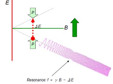
NMR磁场强度测量原理
A proton (hydrogen nucleus) has two possible spin states. In the absence of an external magnetic field, these states are degenerate, but as soon as we apply a field, the spinaligned state is lower energy than the unaligned state. The energy differential ΔE between the two states depends linearly on the magnetic field strength. This exact linear dependence, very nearly independent of all other external factors such as temperature, forms the basis for NMR teslameters.
In an NMR teslameter, a coil is wrapped around a sample material rich in hydrogen nuclei – ordinary water works great. This is the "Nuclear" part of NMR. The sample is placed in the magnetic field to be measured ("Magnetic") and irradiated with an RF signal whose frequency gradually increases. When we hit the frequency that corresponds to ΔE, the sample suddenly absorbs energy ("Resonance"). For a field strength of 1 T, this resonance occurs at about 42.5 MHz; this is the gyromagnetic ratio (γ) for hydrogen nuclei.
The resonance is extremely narrow, and so the frequency provides an extremely precise measure of the magnetic field strength.
NMR has some overwhelming advantages over other measurement technologies:
- extremely precise;
- no drift; and
- measures total field.
That last point is perhaps not obvious. In fact, the protons align themselves with the magnetic field, and the resonance always occurs at B/γ, regardless of how we orient our coil. It turns out, however, that the best coupling between the RF field and the proton spins is achieved when the magnetic field is perpendicular to the coil's axis. In fact, NMR has a blind spot when the coil's axis is exactly aligned with the magnetic field.
NMR also has substantial limitations:
- Uniform field only: In a field gradient, one edge of the sample will resonate at one frequency, and the opposite edge at another. As the gradient increases, the resonance signal becomes broader and shallower, until it can no longer be detected; this limit typically lies in the range of several hundred to several thousand ppm/cm. In some situations, gradient correction coils can improve this situation.
- DC / low-AC fields only: NMR is a relatively slow measurement method, making it unsuitable for measuring rapidly varying fields. Here, we have to distinguish search mode from measurement mode: scanning through a large frequency range to find the resonance requires the field to remain stable for seconds; but once the search is completed, we can track the field and achieve measurement rates of up to about 100 measurements per second.
- Low fields require a large sample, ESR or pre-polarization: As the field and, consequently, the energy gap between the spin states tends towards zero, the populations of the two states tend to become equal, and the strength of the resonance diminishes. There are three possible remedies:
l Use a very large sample to increase the number of spin-flips.
l oPre-polarize the sample in a strong field to populate the spin-aligned state, and then remove this bias field during the measurement.
l Use ESR, i.e. the spin of orbital electrons instead of protons, because these have a gyromagnetic ratio (γ) three orders of magnitude higher than protons.
2. NMR 核磁共振测绘
To build an NMR mapper, we need:
- NMR probe or probe array. As we will see in the example, a probe array ramatically speeds up the acquisition and simplifies the jig.
- Positioning jig.
- NMR teslameter (the electronics).
The output of an NMR mapper is straightforward:
- total field B,
- point-sampled,
In fact, the size of the "points" are determined by the size of our NMR sample, which is typically a few millimetres in diameter.
- very high precision.
Well below 1 ppm, in the best case approaching 1 ppb.
Computational post-processing depends very much on the application. The typical postprocessing for MRI applications is described in the following section.

Close-up of an NMR probe array. Each probe – one of them is circled – is mounted on its
own circuit card. Such probe arrays typically contains 24 or 32 probes (maximum 96).
3. NMR核磁共振测绘 –
The most widespread use of NMR mapping relates to the development, manufacturing and installation of MRI (Magnetic Resonance Imaging) magnets. These can be permanent, resistive, or superconducting magnets, with a typical field strength between 0.2 and 7 T.
Technically, the preferred shape is a torroid, but for improved access to the patient, or for a less claustrophobic feel, C-shaped magnets are sometimes used. Most modern full-body systems from the major manufacturers use superconducting torroids, 1.5 or 3 T, as illustrated in Figure 12.
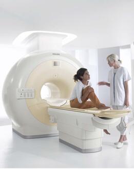
Example of modern full-body MRI scanner (Philips Achieva).
The homogeneity of the field in the imaging region must typically be guaranteed to within a few ppm. Since minor, unavoidable manufacturing variations cause inhomogeneities generally two orders of magnitude greater than that, the homogeneity must be adjusted in a process called shimming.
The overall shimming procedure is to map the field, analyze the map, adjust the field with iron shims and/or shim-coil current adjustments, and to remap the field to verify the results.
If necessary, this process is repeated until the specified homogeneity is achieved. The
same process, and usually the same equipment, is used in R&D, manufacturing and
installation. The measurement is extremely sensitive, and obscure effects such as the
passing of an overhead crane or the return current of a nearby train can cause huge
errors.
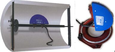
NMR mapping jigs for torroid- and C-shaped MRI magnets, respectively.
The probe arrays and jigs shown in Figure 11 and Figure 13 generate a map of the total field on the surface of a sphere. As long as there are no currents or magnetic material inside this sphere, and assuming the direction of the field is known, the field at every point inside the sphere can be calculated from Maxwell's equations. Generally we use an expansion in spherical harmonics to perform this computation.
It is worth noting that the jigs shown are much simpler that in the previous examples.
Fundamentally, there are two reasons for this:
- Using a probe array reduces the required motion to a single dimension.
- Partly because the field is so uniform, and partly because the NMR sample points are fairly large, the requirements on the positioning precision are much less – typically 0.1mm. Compare that to the 0.1 μm for the Hall mapper example!
4. 问答
To summarize our observations from these different examples of magnetic mapping, here is a small check-list of key questions to ask if you want (rather, need) to build a mapper:
- Use: R&D, production, field service?
It makes a big difference if a system is to be used once in a while for R&D, or all the
time in production, or packed up in a suitcase for field service.
- Measurement: field components, total field, integral, gradient?
Do you really need Bx, By, Bz, or do you really need B, or an integral or gradient of B?
By choosing the appropriate measurement technology, you may be able to speed up
the acquisition as well improve your precision.
- Field: strength, uniformity, AC/DC, stability?
The characteristics of your field also play an important role in the choice of measurement technology.
- Precision: 10% or 10 ppm?
… as does the precision required.
- Positioning: access, range, precision, reproducibility?
The design of your jig is as important as the choice of magnetic sensor. What sort of
access do you have to the region to be measured? What positioning precision do you
need? How reproducible must the positioning be?
- Environment: vacuum, cryogenic?
The environment changes dramatically depending on whether you're in a lab, on a
production floor or in the field. In addition, magnetic systems are often combined with vacuums and cryogenic temperatures. Hall effect sensors, for example, don't work at liquid-helium temperatures.
- Speed: cost, external error sources, human error?
Making a fast mapper may not cost more; for example, we saw that the simplification of the jig may more than make up for the costs of a sensor array. In addition, the improved speed dramatically reduces external and human error.